
Diy FatShark Diversity

For a long time now I have been trying to reject the fact that i really need to buy new FPV goggles. My current ones are low resolution and only have 8 channels but they still work, making it hard to justify spending ludicrous amounts of money replacing them. The only real extra features to be found on newer models is that they have external receivers allowing you to install custom diversity modules that support more channels.
I thought to myself . . .why cant i just add these features to my current goggles. So i created the Diy FatShark Diversity.
For electronics hardware i purchased a cheep diversity diversity reciever from banggood ( http://www.banggood.com/DIY-RX5808-5_8G-40CH-Diversity-FPV-Receiver-with-OLED-Display-for-FPV-Racer-Quad-p-1051163.html ) .
This is based off of the fantastic rx5808-pro-diversity project by Sheaivey on github ( https://github.com/sheaivey/rx5808-pro-diversity ).
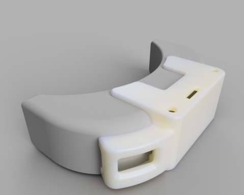
I then set about designing an enclosure to house this that would conform to my current goggles. I have recently been experimenting with using Fusion360 to design parts ( you can get a full featured version for free as a hobbyist). I decided that would be my first serious project in Fusion360. i managed to come up with the following result in just 2 evenings. renders were done using the inbuilt rendering tools.
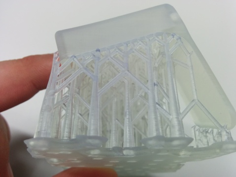
I printed this part on a FormLabs “Form 1” SLA 3D Printer in clear resin.
This required a small amount of cleanup to remove print supports but overall i was pleased with print quality.
Assembly was relatively straight forward, only requiring a small amount of manual filing around the antenna holes as the board must be inserted at an angle before being able to lie flat.
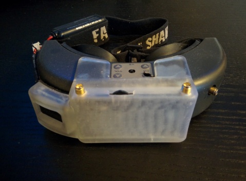
The unit is powered from the balance port on the goggles and uses the aux jack on the goggles to provide video, this mean that the goggles remain unmodified if i ever want to sell them.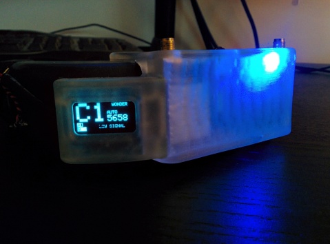
These new goggles now have all the channels supported by newer models but also have diversity and frequency scanning capability which is not even avalable on the most expensive stock goggles.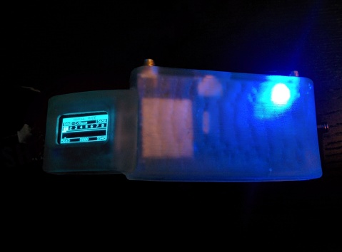
Hopefully these upgrades will help me reject the fact that i need to upgrade for a little longer.
Files can be found on my Thingiverse at http://www.thingiverse.com/thing:1658524
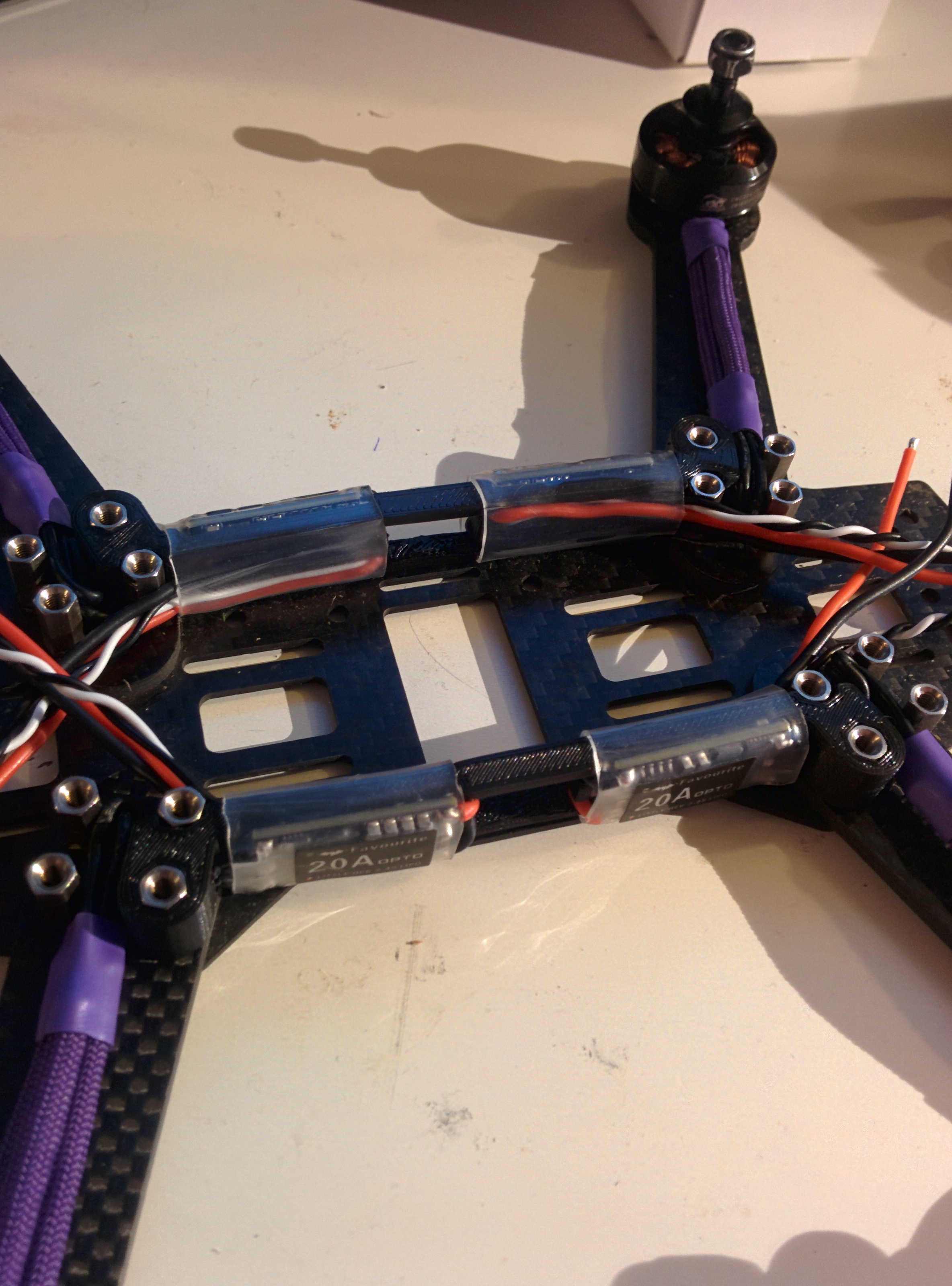
ZMR250 Lowrider 20A ESC Spacer

Just a quick post to say that i have uploaded one of my parts from my newest ZMR build to Thingiverse, check it out:
http://www.thingiverse.com/thing:1057019


Printing new things for my new things
 Over the past few days I have been having great fun flying my new Hubsan X4 Quadcopter. This is an amazing gyro stabilised RC quadcopter that is small enough to land in the palm of your hand. It can fly perfectly indoor or out and has enough lift to carry a key chain camera. Only problem is after reading on the forums I realised that the small blades are fragile and can easily become damaged during crashes. Many Quadcopters such as the Parrot AR drone have prop-guards to protect the props from impacts and so I decided to design a set for the Hubsan X4.

These parts were printed on my printrbot and the design files can be found on Thingiverse (http://www.thingiverse.com/thing:61127). The bumper weighs about 4 grams in total and is completely push fit. flight time is slightly reduced as you would expect but this is easily outweighed by the fact that bumps with walls and objects no longer stop the props (causing the quad to fall from the sky).
In the future I may re-design this to be a bit stronger / lighter if I get the time but till then I thought some one might find this useful.
Printrbot PSU upgrade
The place that I work often throw things away that are useless to them, however this does not mean that they useless things.Being a student on tight budget you learn that it would be pointless to waste nice things that get thrown out. This week I managed to pick up a 350W ATX powersuply.
My printrbot came with a 250w psu so this would make a nice upgrade. Because the new one cost nothing i can hack/mod it without feeling to bad if I break it. The original powersupply had ALL the cables you would usually find inside a computer, as 90% of these were not needed they ended up just getting in the way. the printrbot also requires a link inserted in the powersuply to turn on, this link often comes loose and I don’t trust it during long prints.
After opening the supply I cut out all unnecessary cables then de-soldered the loose ends from the PCB. I wired the start-up line to ground so that the unit is always on then bradded the power cable to tidy it up. As it runs very quietly I also decided to add a small red led strip inside so that I can see when its on. I have also found that the printrbot cable management is not great and the bed often catches trailing cables from the extruder. Messy cables annoy me and I decided to fix this. I bradded all cables that go to the extruder as well as the x stepper cables and bed cables.
") Happy with today’s work I can now relax knowing that Sunday has not been wasted.
Happy with today’s work I can now relax knowing that Sunday has not been wasted.
Line follower first prototype.

earlier this month i attended robotic2012 in Birmingham to watch the UK micro-mouse competition. After building a micro-mouse last year for a project it was really interesting to speak to some of the best in the country. whilst there we also got to see some of the other competitions they were running such as drag and robot tracer.
Robot tracer is an event where a robot has to follow a white line on a black surface around a course, you usually get up to 5 runs to set a best time. the robot who completes the course in the quickest time wins. many of the robots that entered this year seamed relatively slow and many were made from “off the shelf” robots, some even used stepper motors to drive the wheels. having built many simple line followers it seamed like it would be relatively easy to build a small line follower that could easily outrun the slower bots.
so what sets this competition apart from previous line followers i have built?
the interesting thing about robot tracer is that the course is made up of straight sections and curves of set radius. on the track there is a marker at the beginning and end of every curve or straight section as well as markers for the begging and end of the circuit. this means that if you can read the markers you could easily learn the course on your first run and then adjust speeds for your other runs (faster on straights and slower on tighter curves). most of the robots that entered this years competition were not able to read these markers and did not learn the course, limiting top speed.
i have decided to try and build a line follower to enter next years competition. i intend on building a small, light robot capable of learning the course. this will require the robot to have some sort of encoders to record position as well as accurate control of wheel speeds.
First prototype.
after doing some research i have purchased some small pololu gear-motors for the robot as well as an atmega 328 based microcontroler with a motor driver. at the moment this has been mounted to a breadboard for easy prototyping and is running off a spare 7.4v battery from my micro-mouse (far to big). i am currently using tires from some Solarbotics RW2i wheels however i have printed my own hubs for these, along with a prototype chassis to hold everything together. this is only a rough design and i intend to make it allot smaller eventually however this will make testing ideas very easy.
plan now is to work out some sort of control for the robot (either Bluetooth or small RF transmitter) and also work out how i can add encoders to the motors.
Getting my print on again.
Getting my print on again.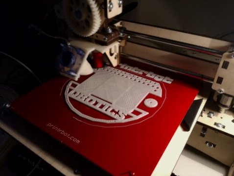

Printing cookie cutters
Printing cookie cutters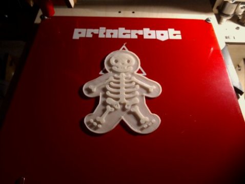

attempt to print cookie cutter 😛
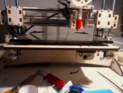
Print bed upgrade . . . Kind of
So today I decided to upgrade my print bed to something a bit stronger. I have read that many people use a glass printbed so decided this would be a good idea.
firstly I found a piece of mirror that was the correct size. I realised that I needed to drill holes in the corner to screw it down. 4 mm in and 1 drill battery later I realise that you cant drill glass without a glass drilling bit. TO PLAN B, I cut the corners off and mounted this to my print bed with the protective frame corners that the mirror came with. whilst I had the print bed off I also added some cardboard to the under side to provide some insulation as I have been having problems getting the bed to temperature. When I powered it up I instantly noticed it was heating up much quicker and when it reached temperature it was much more stable.
 It seamed to be going well but then as I started printing I realised that nothing was sticking to the bed. the surface of the glass is to smooth for the ABS to grip to. I tried to rough it up with some sand paper but this didn’t have much effect. after doing some research it turns out that glass is only suitable for PLA. some have had success with sand blasted glass but as I don’t have a sandblaster to hand I cant really try it.
 LESSONS LEARNED :
1. insulating the underside of your heat bed makes a big difference.
2. glass print beds should not be used when printing ABS
3. don’t try to drill holes in glass, if you don’t have the correct equipment its just not going to happen.
After some calibration I’m printing at 0.1mm layer helight.
 After some calibration printing at 0.1mm layer height looks reasonable
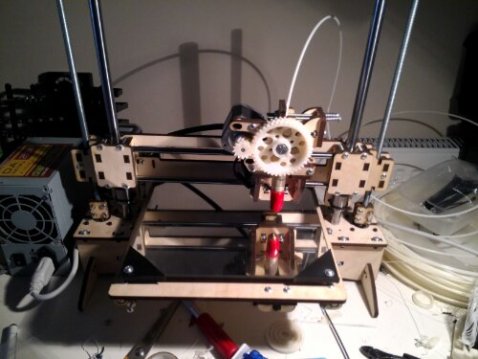
First print on my printrbot plus
 First print on my printrbot plus
